Introduction
I have installed a small photovoltaic system to charge batteries which power the house lighting circuit via an inverter. The system has been operational since late 1999 and there have only been a few occasions when it has been unable to supply all my lighting needs.
System Details
Outside
Solar Panels
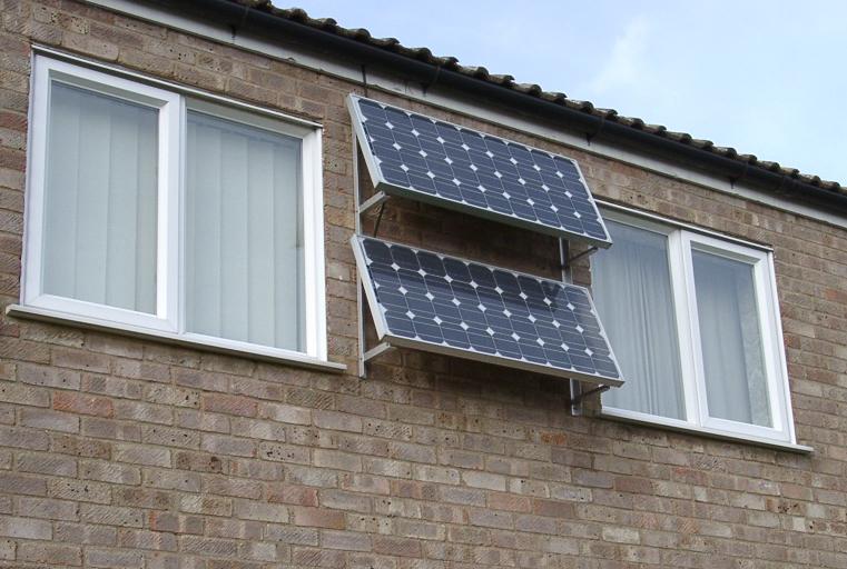
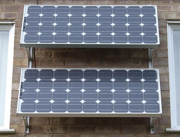
The system uses BP solar modules of type BP 275F which have a nominal voltage of 12V and a peak power of 75W. Two of these are connected in series to form a 24V, 150W array. They are mounted on the front wall of the house between the bedroom windows.
Batteries
The original setup

These are Halfords leisure batteries. Two 12V units are connected in series to suit the 24V system. They are mounted in a meter box on the outside wall of the house. I’m not sure what the actual capacity is but I would expect a minimum of 60Ah.
The upgrade 17 August 2001
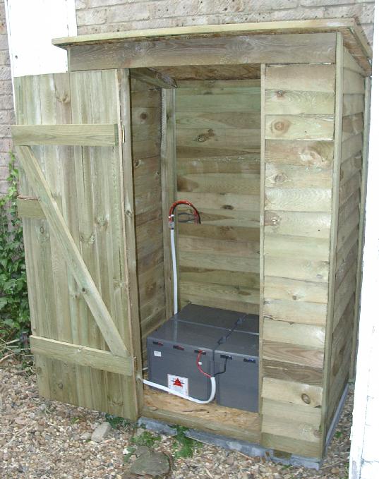
These are Tungstone Challenger Plus batteries. Each unit consists of 3 individual cells which have been strapped in series to form a 6V battery. Four of these connected in series provide a total of 24V at 160Ah. A wooden ‘wall store’ houses the batteries and this is located against the outside wall of the house, where the original meter box had been mounted, allowing the existing wiring to be used.
The replacement 4 July 2006
One of the cells of the previous battery setup has failed short circuit. This actually happened some time ago but it has taken me a while to get around to buying replacements. I’d been wondering what to get but eventually went for a ‘least hassle’ option, rather than a technical decision, so that at least I’d have something operational again. The local motorist centre sells 110Ah leisure batteries at a reasonable price so a pair of these have now been installed.
Inside
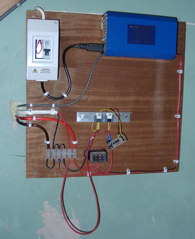
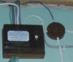
A wooden board mounted under the stairs holds the indoor part of the system. The battery wires pass straight through the wall and the feed from the panels runs down inside the wall cavity from the loft. A length of multicore cable, which is currently unused, runs out to the battery box and can be seen in the photograph with its free end tucked behind the inverter. The existing mains consumer unit is also under the stairs on the end wall to the right of this board.
Charge Controller
The original setup
This is a shunt regulator based on a module designed and built by Bernie Wright. It can be seen hanging by its wires in the photograph. The output configuration is modified slightly so that it can directly drive the gate of a power FET with no other external components. The FET is wired directly across the feed from the panels and shorts them when it is driven. A series diode and fuse are placed in the feed to the batteries. The FET and diode are mounted on a heat sink made from a piece of aluminium angle left over from the solar panel support frame.
The replacement 10 July 2006
While installing the new batteries I managed to break one of the leads of the FET used in the original controller. Rather than rebuilding that controller I decided to obtain a commercial controller which would have the advantage of providing some monitoring capability as well as giving better charging characteristics. The chosen device was the Steca PR1515 which has an LCD to display various information and uses PWM charging based on a calculated State Of Charge value.
Inverter
This is an ASP “Piccolo 24” and is a true sine wave inverter which means that it can be used to power most types of equipment. In practice all my lights are low energy fluorescents which aren’t sensitive to waveform (and in fact will even run on DC) but I thought it might be more versatile for possible future uses. One other advantage is that the output is transformer isolated which allows its neutral to be commoned with the mains neutral while still keeping the battery negative at earth potential.
The following data is taken from the supplied manual.
| Rated power Pnom (1Std. TA=20 deg. C) | 250W |
| Efficiency max. app. | 92% |
| Nominal input voltage UDCIN | 24V |
| Input voltage range | 21-32VDC |
| Output voltage | 225VAC +/- 5% (true sinewave) |
| Output frequency | 50Hz +/- 1% |
| Load power factor COS PHI | 0.5-1 |
| No load power draw 225VAC ON | 2.5W |
| Toroidal transformer | IEC 742, VDE0551 |
| Temperature range | 0-50 deg. C (<95% not condensing) |
| Fan | Hysteresis controlled, 55 deg. – 45 deg. C or high load |
| Dimensions BxHxT | 110×75 x 190 mm |
| Weight | 2.5 kg |
| Enclosure | IP20 |
| DC-Wire | ca. 70cm, 2.5mm2 |
| AC-Outlet | inbuilt outlet |
| EMV/Immunity | complies with CE rules |
Mains Interconnection
The existing lighting circuit feed, having been removed from the consumer unit, is taken to a junction box. This is supplied by two feeds, one from the inverter (via an MCB) and one from the consumer unit. A run of 3 core and earth carries the two live feeds and a common return to a two-way light switch which is used to select either battery or mains supply.
Conclusions
The original battery system did not have enough capacity. The occasions when power ran out were due to a series of about 3 dull days where no significant charging current was generated. Typically a brighter day followed within a day or two of the charge running out and even in winter a bright morning could replace a single evenings usage before noon.
The new higher capacity battery system will hopefully be able to store enough power to cope with a week of dull winter days but whether that will be sufficient to allow uninterrupted operation through the winter remains to be seen. UPDATE – The higher capacity does provide power for a week. However if power does run out it also takes more sunny days to recharge the flat batteries sufficiently for the inverter to come back on. So the benefit of a higher capacity rather depends on the weather patterns.
In summer the high sun angles in the middle part of the day result in partial shading of the lower panel by the bottom edge of the upper one. If I had mounted them further apart the lower panel would have been further down the wall and in winter mornings with low sun angles it would be shaded for longer by the house opposite. In practice the low demand in summer means that there is still sufficient charge generated in early morning and late afternoon.